By keyes | 09 November 2018 | 0 Comments
How to Simulate Your Traffic Light
Introduction
In our daily life, it's indeed common to see the traffic light when crossing the road.
To follow the traffic regulation, we often said, red for stop and green for go. Cross the street when the traffic light turns green.
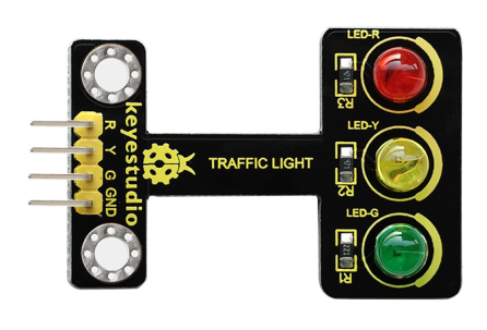
You may be curious to know how the light work. So we today introduce the new keyestudio traffic light module.

When learning the microcontroller, you may usually use three LEDs, namely red, green and yellow light to simulate the traffic light blinking via external connection.
Now you can use this module to simulate the traffic light system, which is very convenient for wiring. And on the module you can see the red, yellow and green LED are integrated together, more easier for you to connect the lines.
This module is fully compatible with Arduino microcontroller and raspberry pi system, so you can also apply it to Arduino or your PI. It enables you to make interaction with light-related works.
Next, let's move on to use this module to simulate a simple traffic light.
Connection Diagram
Well, prepare all the hardware, you can go to connect the board, really simple to follow.
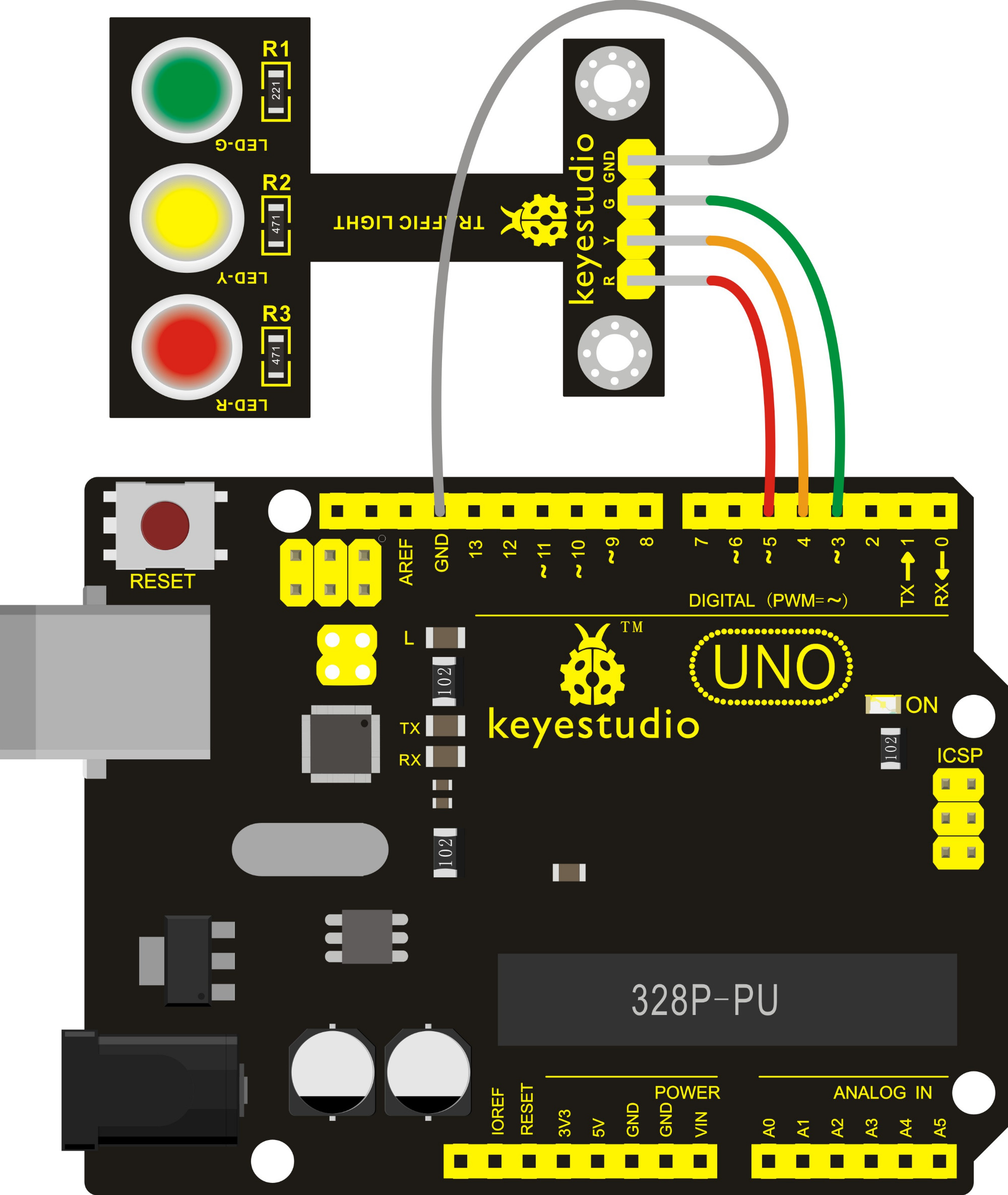
For the traffic light module, connect R pin to UNO digital 5, Y pin to digital 4, G pin to digital 3 and GND to GND.
Finally, you should get the connection as the following diagram shown.

Upload the Code
Check out the following code: upload the code to Arduino IDE
int redled =5; // initialize digital pin 5.
int yellowled =4; // initialize digital pin 4.
int greenled =3; // initialize digital pin 3.
void setup()
{
pinMode(redled, OUTPUT);// set the pin with red LED as “output”
pinMode(yellowled, OUTPUT); // set the pin with yellow LED as “output”
pinMode(greenled, OUTPUT); // set the pin with green LED as “output”
}
void loop()
{
digitalWrite(greenled, HIGH);//// turn on green LED
delay(5000);// wait 5 seconds
digitalWrite(greenled, LOW); // turn off green LED
for(int i=0;i<3;i++)// blinks for 3 times
{
delay(500);// wait 0.5 seconds
digitalWrite(yellowled, HIGH);// turn on yellow LED
delay(500);// wait 0.5 seconds
digitalWrite(yellowled, LOW);// turn off yellow LED
}
delay(500);// wait 0.5 seconds
digitalWrite(redled, HIGH);// turn on red LED
delay(5000);// wait 5 seconds
digitalWrite(redled, LOW);// turn off red LED
}
Phenomenon
Powered up and the code is uploaded successfully, three LEDs on the module will automatically start to simulate the traffic light running.
You can see the green LED on for 0.5 seconds then off, followed by yellow LED blinks for 0.5 seconds then off, and red LED on for 0.5 seconds then off, circularly.
If you want to turn LED on more faster, you can set the delay time in the code and upload the code again to check it.
Further
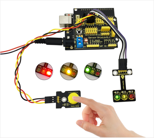
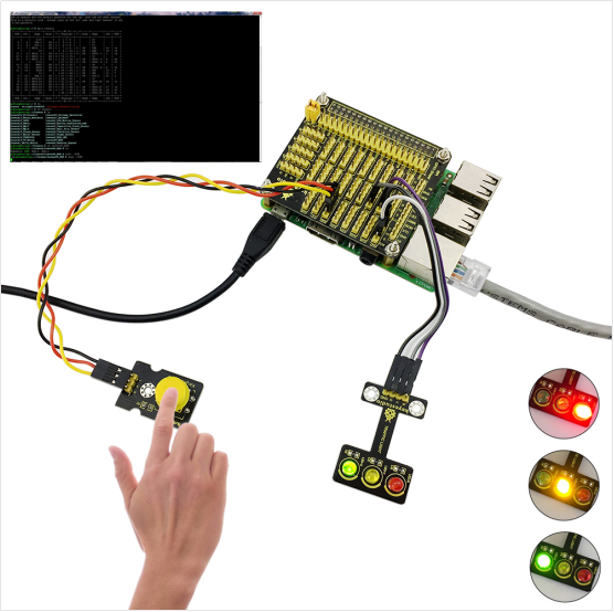
Besides, you can extend it to use the button to control the LED on and off, using UNO board or RPI shield. Below are two examples for your reference.


Wish you can learn more from this module.
Have any questions or advice about this? welcome to leave your comment here.
To follow the traffic regulation, we often said, red for stop and green for go. Cross the street when the traffic light turns green.
You may be curious to know how the light work. So we today introduce the new keyestudio traffic light module.

When learning the microcontroller, you may usually use three LEDs, namely red, green and yellow light to simulate the traffic light blinking via external connection.
Now you can use this module to simulate the traffic light system, which is very convenient for wiring. And on the module you can see the red, yellow and green LED are integrated together, more easier for you to connect the lines.
This module is fully compatible with Arduino microcontroller and raspberry pi system, so you can also apply it to Arduino or your PI. It enables you to make interaction with light-related works.
Next, let's move on to use this module to simulate a simple traffic light.
Preparation
Jumper wires*4
USB cable*1
Connection Diagram
Well, prepare all the hardware, you can go to connect the board, really simple to follow.
For the traffic light module, connect R pin to UNO digital 5, Y pin to digital 4, G pin to digital 3 and GND to GND.
Finally, you should get the connection as the following diagram shown.

Upload the Code
Check out the following code: upload the code to Arduino IDE
int redled =5; // initialize digital pin 5.
int yellowled =4; // initialize digital pin 4.
int greenled =3; // initialize digital pin 3.
void setup()
{
pinMode(redled, OUTPUT);// set the pin with red LED as “output”
pinMode(yellowled, OUTPUT); // set the pin with yellow LED as “output”
pinMode(greenled, OUTPUT); // set the pin with green LED as “output”
}
void loop()
{
digitalWrite(greenled, HIGH);//// turn on green LED
delay(5000);// wait 5 seconds
digitalWrite(greenled, LOW); // turn off green LED
for(int i=0;i<3;i++)// blinks for 3 times
{
delay(500);// wait 0.5 seconds
digitalWrite(yellowled, HIGH);// turn on yellow LED
delay(500);// wait 0.5 seconds
digitalWrite(yellowled, LOW);// turn off yellow LED
}
delay(500);// wait 0.5 seconds
digitalWrite(redled, HIGH);// turn on red LED
delay(5000);// wait 5 seconds
digitalWrite(redled, LOW);// turn off red LED
}
Phenomenon
Powered up and the code is uploaded successfully, three LEDs on the module will automatically start to simulate the traffic light running.
You can see the green LED on for 0.5 seconds then off, followed by yellow LED blinks for 0.5 seconds then off, and red LED on for 0.5 seconds then off, circularly.
If you want to turn LED on more faster, you can set the delay time in the code and upload the code again to check it.
Further
Besides, you can extend it to use the button to control the LED on and off, using UNO board or RPI shield. Below are two examples for your reference.


Wish you can learn more from this module.
Have any questions or advice about this? welcome to leave your comment here.
Leave a Reply
Your email address will not be published.Required fields are marked. *
CATEGORIES
TAGS